Difficulties with hesitation lines with short shot moulding and limitations with the size of gas channels with full shot moulding lead to the development of overflow or spill wells. Overflow wells allow the moulding to be filled and packed with plastic before gas injection. Gas flow into the cavity is not limited to the shrinkage of the plastic as with full shot moulding.
The overflow well allows large amounts of plastic to be displaced out of gas channels into a well outside the component cavity. This well is linked to the component cavity by a gate and runner system.
Most styles of moulding can benefit from the use of this method including all described in the full shot and short shot moulding process.
Wall thickness is usually between 2 and 4mm but because plastic packing can be used prior to gas injection thicker sections can be used without the problem of uncontrolled gas penetration.
Ribs and thick sections between 2 and 6mm are typical but can be up to 20mm.
The considerations given to the plastic filling phase are the same as with injection moulding. The filling pattern needs to be designed to avoid weld lines, flow marks and air traps.
The moulding is filled to at least 100% of mould cavity volume with plastic during the plastic filling stage. Depending on the design and plastic use plastic packing will be used to avoid sink over standard injection moulding features and stabilise the plastic in general wall sections.
In most cases the path to the overflow is closed during plastic injection and packing. The path to the overflow is opened and gas injected. The gas takes the path of least resistance as it flows through the moulding displacing the plastic into the overflow well. The overflow well is filled and the gas continues to apply packing pressure to the surrounding plastic.
The rate of flow of gas into the component is controlled by the rate of plastic flow into the overflow well. The amount of gas flow into the component is controlled by the size and shape of the gas channel and the volume of the overflow well.
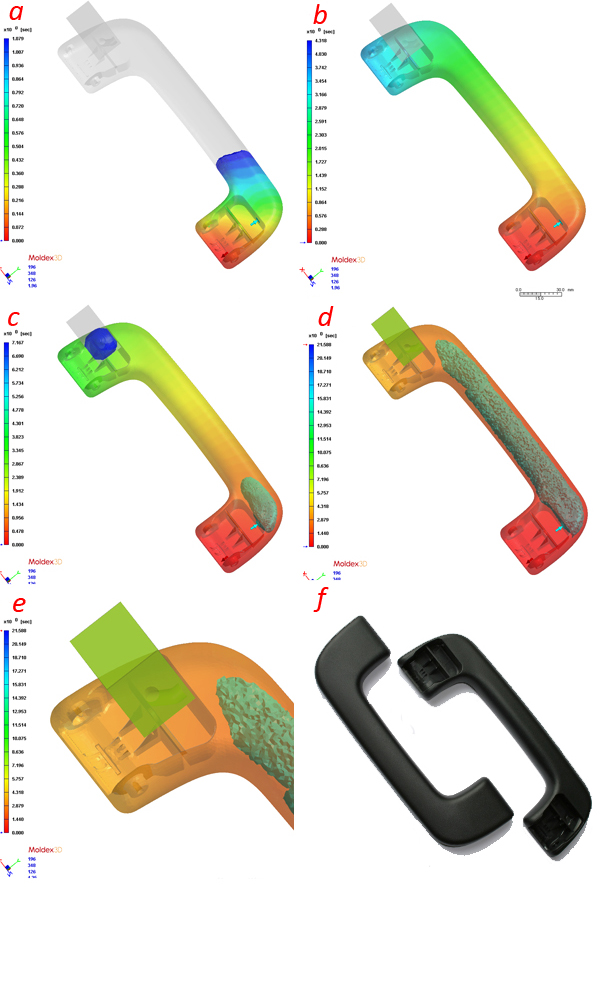
The pictures show the results of the flow analysis on a steering wheel. The analysis shows the use of 2 overflow wells to achieve the desired gas flow through the component. The flow analysis completed by us allowed the component to be successfully modified, the tool build and production to start without the need for any modification to the component design or mould.
Overflow wells step by step:
a Plastic injection starts, the paths to the overflows are closed.
b Plastic fills the cavity and plastic packing starts. Plastic packing continues until the injection moulding features and wall section has been packed and stabilised.
c The path to the overflow is opened and gas injection starts. The gas takes the path of least resistance, the hot core in the centre of the gas channel, as it flows towards the overflow well.
d The overflow well is sized to allow the gas to flow the full length of the wheel. The overflow fills and gas packing starts.
e Overflow wells allowed plastic packing to be used. Plastic packing achieved a good surface finish and packed the centre of the component avoiding uncontrolled gas penetration.
f Shows a picture of the finished component.
Advantages
> Maximum component design flexibility. Large gas channels fully gas cored without hesitation lines.
> Large gas channels fully gas cored without hesitation lines.
> Plastic packing improves surface finish and avoids gas penetration.
> Best surface finish
> Direct control over the length of the gas flow using the size of the overflow well
> Control over the thickness of the gas channel wall section using plastic packing
> Control over gas penetration
For more information please contact us.
Limitations
> Slightly reduced size of the gas core compared with short shot moulding
> More complex tool design
> Recycling/reprocessing of the overflow wells